Over the last few decades of successful HFC Network development cable operators have installed many systems to support their operational activity (OSS). Network maintenance departments of MSOs have developed and implemented internal procedures for using these systems, without which they can’t plan the daily practice of network adjustment, monitoring or troubleshooting.
Such legacy equipment and software, use bi-directional transmissions between field devices and equipment installed in the Headend (HE) or Hub, mostly in a vendor specific, proprietary format. These communications, even if based on standards, like HMS for HFC Network Management, are not using the DOCSIS or DVB-C format, therefore these signals are referred to by the MHAv2 specification as OOB (Out-of-Band) systems.
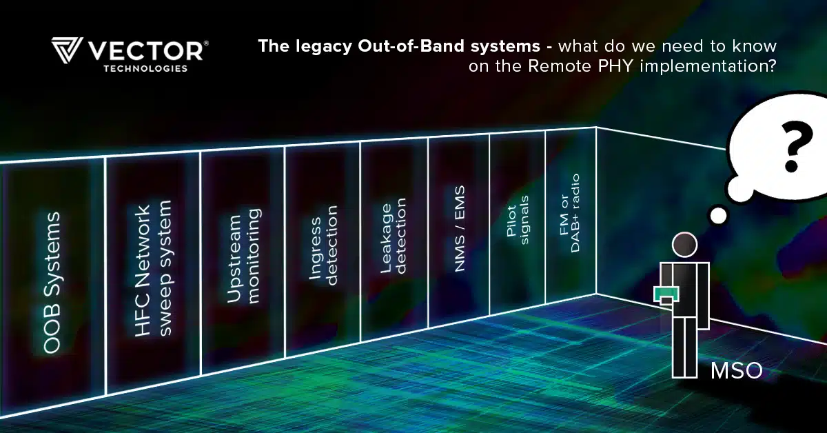
Typical Out-of-Band systems deployed by MSOs: Physical layer signaling for digital MPEG video delivery to STBs (SCTE 55-1 and 55-2). These two signaling systems are not deployed widely in Europe. In America, the millions of set-top boxes deployed remain dependent upon this legacy communication. Therefore most of the standardization work done by CableLabs® within Remote-Out-of-Band Specification as a part of the MHAv2 standard, focus pragmatically on that problem only.
Pilot signals used in HFC distribution active network equipment for the Automatic Level and Slope Control (ALSC).
In the past, it was usually the case that two Carrier Wave signals (pilots) were added in the downstream, one at the beginning of the band and one at the end of the band. It allowed for easy alignment of the active network equipment. These pilots were generated by special HE/HUB Pilot Generators. However modern ALSC circuits and test equipment are able to measure the level of practically any types of RF signals, including SC-QAM signals and even OFDM signals. The signals generated in the RPD can be used instead of pilots transmitted from HE/HUB.
Upstream Monitoring – to detect impulse noise and distortions in the upstream coming from the access network to HE. Specialized high speed multi-channel upstream monitors are often installed in the HE or HUBs.
Ingress Switches control signals sent from the HE controller to activate ingress switches installed in outside plant equipment like optical nodes or RF amplifiers in order to switch off completely or add attenuation in the return path. Often combined with Upstream Monitoring, the controller enables the system to initiate automatic or manual ingress localization procedures after ingress distortions are detected in the HE. An operator or automatic controller can localize the ingress source within the accuracy of the last active device by observing the reduction or disappearance of distortions after activating the ingress switch in the next device. Generally, such communication signals use robust narrowband FSK modulation.
Leakage Detection Systems – to allow Hand Held measurement leakage detectors to distinguish signals distributed in the measured network from other signals detected from the air.
Sweep systems for Network Alignment in both the downstream and upstream direction. MSOs are in the process of deciding if the systems without analogue optics and long RF amplifiers cascades sweep systems are still relevant, or to use PNM systems utilizing FSC mechanisms implemented in new Cable Modems.
Network / Element Management Systems (NMS / EMS) use a HMS protocol. However, some of the NMS transponders/systems use DOCSIS data transmission not Out of Band and the introduction of Remote PHY and Digital Optics will not affect their operation, as long as a relevant version of DOCSIS is supported.
FM or DAB+ radio signals are not part of OSS, but rather a valuable customer service, however technically the problem is exactly the same as with other OOB signals so we may discuss them at this point as well.
Generally, the problem with OOB signals in new Distributed Access Architecture (DAA) is caused by breaking the analogue RF connection between the HE/HUB and Optical Node. Introducing Digital Optics will produce the effect that some of the existing RF signals can’t be transmitted using the same natural easy way as before.
Therefore, together with the implementation of Remote PHY in the HFC Network, the proper solution for legacy OOB systems needs to be developed and implemented.
A short term solution could be the implementation of an RF overlay, that is, maintaining analogue optics in parallel to digital ones. Such a solution is transparent for OOB signals but does not provide all of the benefits as “pure Remote PHY” – as RF management and analogue optics shelfs are still occupying space in the HE/HUB racks. Additionally, it is important to remember about proper level aligning and minimizing the effect of noise floor combination.
As a middle term solution, the Narrowband Digital Forward / Narrowband Digital Return (NDR/NDF) technology, described in the Remote-OOB Specification from the MHAv2 standard set, can be used. Initially designed for legacy two way signaling for digital video delivery to STBs signals, these technologies transmit digitally sampled parts of the RF spectrum and can be used for other legacy OOB signals. As NDF/NDR channels have limited bandwidth more than one may be needed. For example, one NDF channel can be entirely used for FM radio while the other will transmit all other OOB signals (sweep telemetry, leakage tags, ALSC pilots, HMS, ingress switch control).
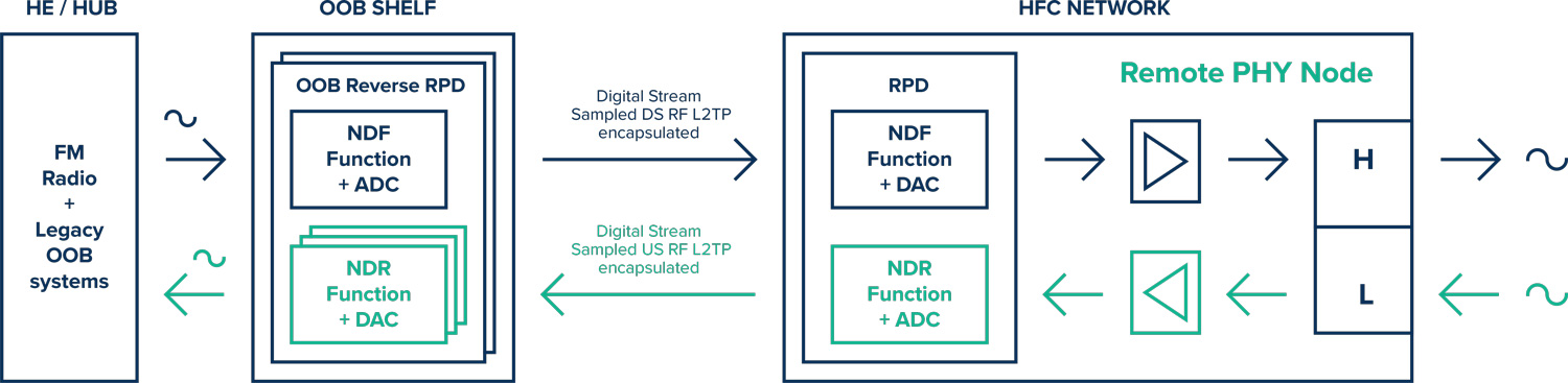
It is important to remember that every additional supported channel will increase the power consumption of the RPD, and consume some bandwidth between the CCAP Core and R-PHY Node. To allow for transparent transmission, OOB signals must be implemented at HE/HUB as well, by a special, so called, “reverse RPD” module which means that additional equipment is required at that location.
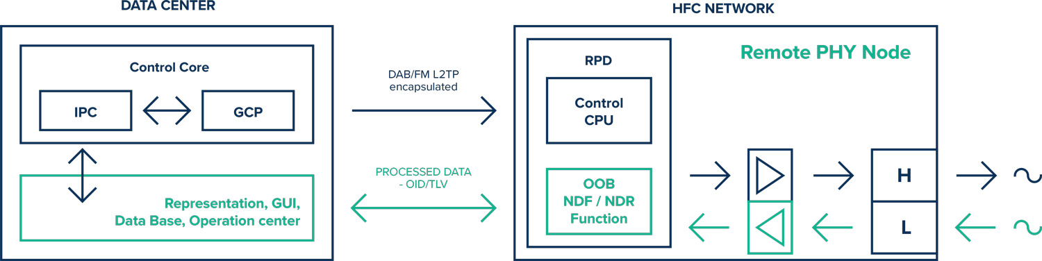
OOB signals can be generated by the RPD. For example, it is possible to send a radio program content as an IP Transport Stream and then generate some part or whole FM radio band at the original frequencies and modulation format in the Remote PHY Node. It is also possible to generate pilot signals, modulated telemetry signals for HMS and Ingress Switches, or tags for leakage detection systems. Using FPGA based RPD produces significant flexibility to adjust to specific operator’s needs while optimizing power consumption at the Node and removing unnecessary OOB features.
Another long term solution would be replacing some of the old legacy OOB systems with modern Proactive Network Maintenance (PNM) tools. With no analogue optics and shorter RF amplifier cascades, some of the older maintenance systems will become less important or even irrelevant. Very powerful micro-computers which are used by the RPD can use a portion of their recourses for distortion detection (like Common Path Distortion localization).
It would be difficult to find one solution suitable for all MSOs and their needs as to OOB communication for OSS.
An optimal solution would probably be a combination of NDF / NDR technology with the generation of some other OOB signals by RPD at the optical node. Also, some of the old legacy OOB will be replaced by the PNM tools.
Ultimately, solutions will depend on the needs of specific operators and will be developed in cooperation between vendors of CCAP Core, RPD and measurement / maintenance systems. It would be good to have the possibility of adding specific features at the RPD (for example based on FPGA flexibility).
About VECTOR TECHNOLOGIES
VECTOR TECHNOLOGIES is part of VECTOR GROUP – dynamically growing European technology consortium operating in the global markets. It draws from a wide experience and competences that VECTOR has accrued over 25 years of its business activity.
VECTOR TECHNOLOGIES is aimed to meet the fast growing demand of telecommunication market for dedicated solutions to maximize business efficiency. We focus on excellent recognition of challenges and conditions of the customer side in the field of fixed access infrastructure.
To learn more visit: www.vector.net.


